
3D printing a programming jig and embedding pogo pins
21 September 2020When using a microcontroller in a custom design, there’s always a bit of a headache for me because I need to figure out a convenient way break stuff out for programming and development.
Usually you can’t afford to have the “plug and play” comfort of a development board on your custom board. And it’s great to be able to break out more stuff than just the programming ports.
Here I explain an easy way to make a nice programming jig that can break out many signals for custom designs.
It is based on Eagle and Fusion 360 but you don’t need to use those tools. The main things you need are:
- access to an SLA 3D printer (can order online for cheap!)
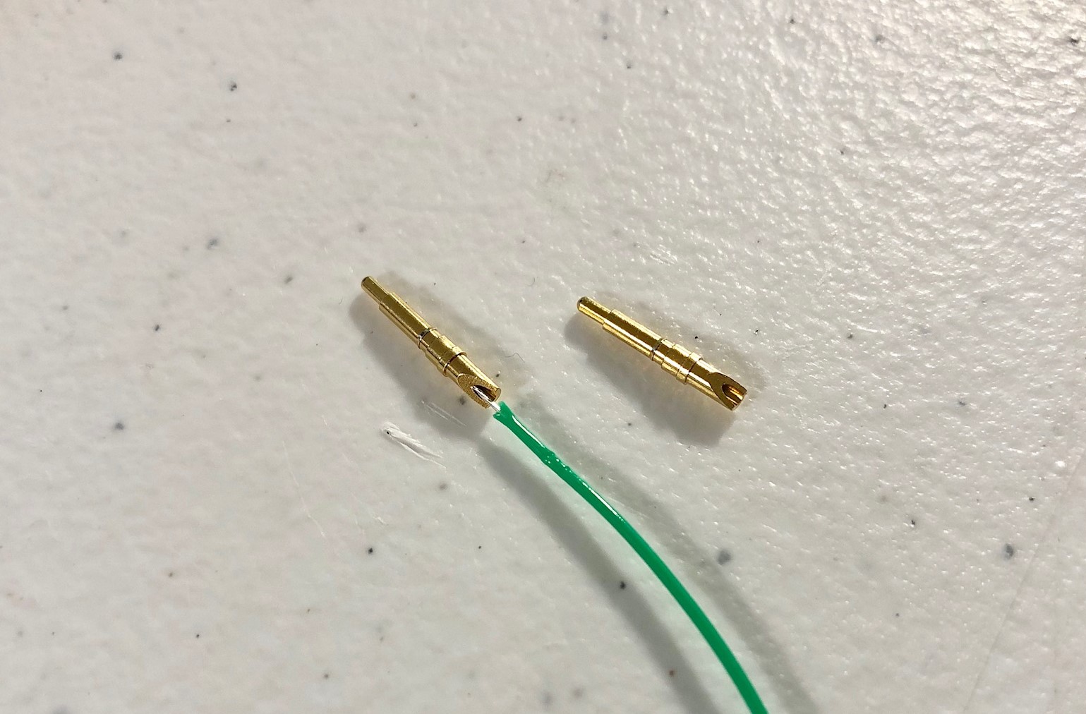
- spring-loaded, solder-cup pogo pins (these are the best I’ve found).
- soldering iron.
Design your circuit
Here is the backside of my circuit.
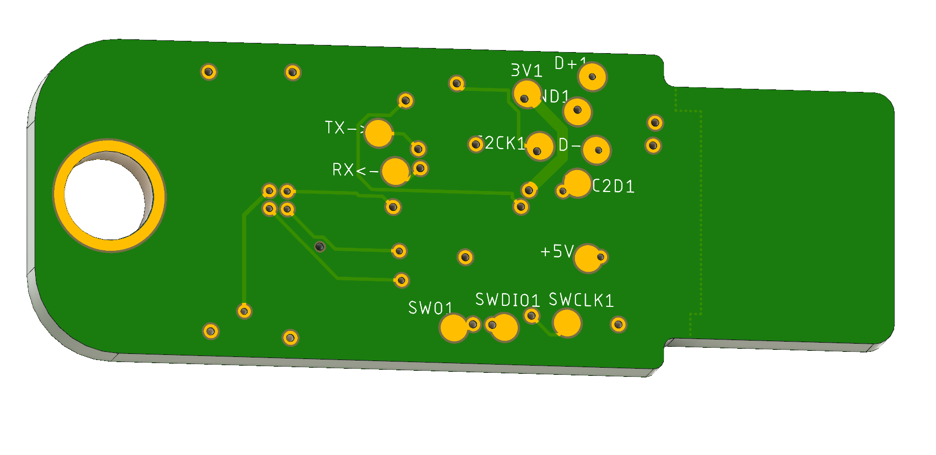
I put little test ports on the back side for every signal that I potentially would like to break out. I didn’t want to adhere to a 2.56mm x 2.56mm grid because that would strain the layout. I just made sure to keep them at least 1.27 mm distance from each other. It is pretty easy to break out signals this way, even when the layout is crowded.
Design the jig
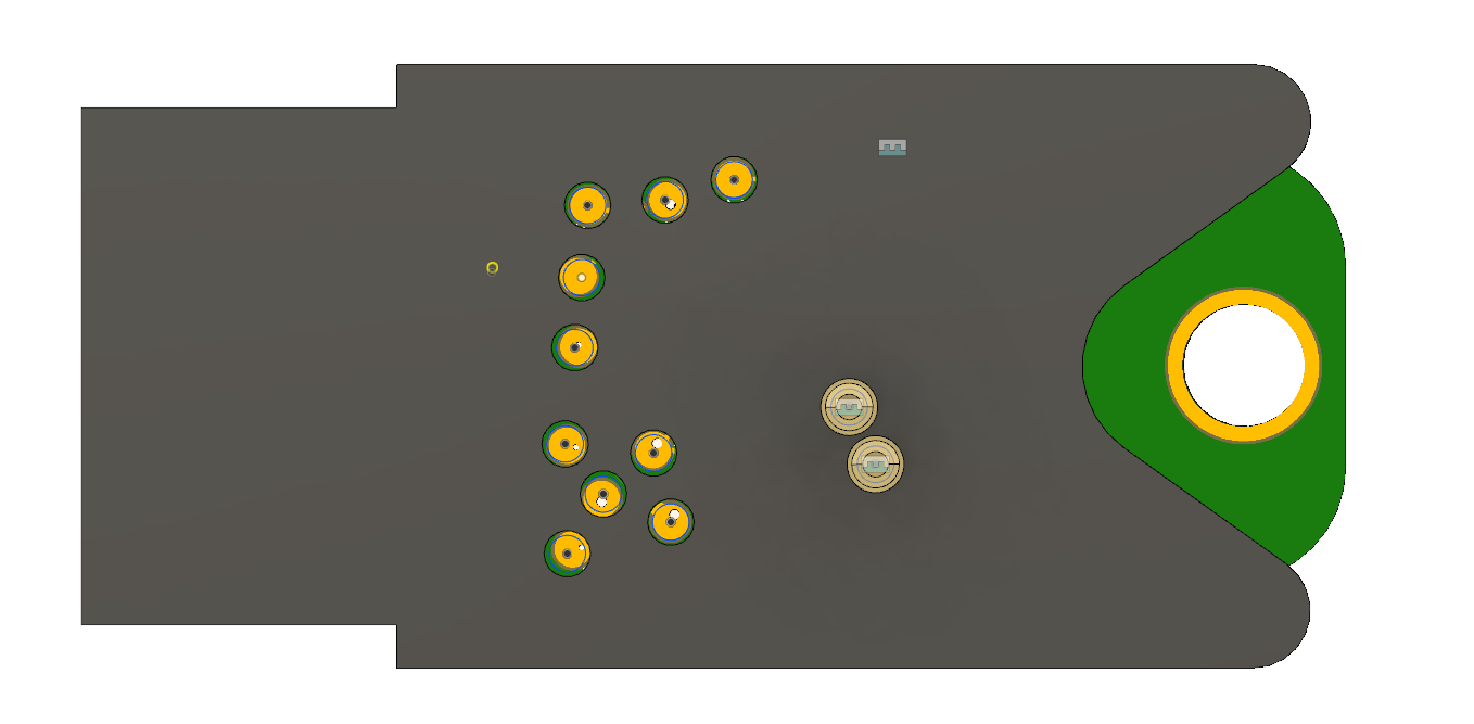
Then, I exported my board from Eagle to Fusion 360 and took a minute to draw up a jig.
It’s a pretty basic design. It just needs an outline to fit the circuit and a cutout so it’s easy to get out. Since this is going to be 3D printed, you can go wild with your design.
Then, draw some circles where all the test pads are and cut them out of the jig. I just eye balled everything, didn’t need to take any measurements.
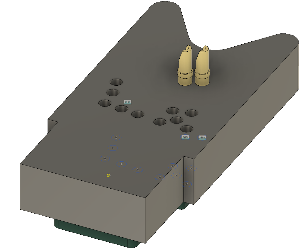
I also included the pogo-pin models from the manufacturer to make sure they fit right. These particular pins are nice because they are both solder-cup and spring loaded. The pitch is about 2.2 mm which is the smallest I could find. Thanks Mill-Max!
Print the jig
I printed the jig on my Form 2 printer. It came out well.
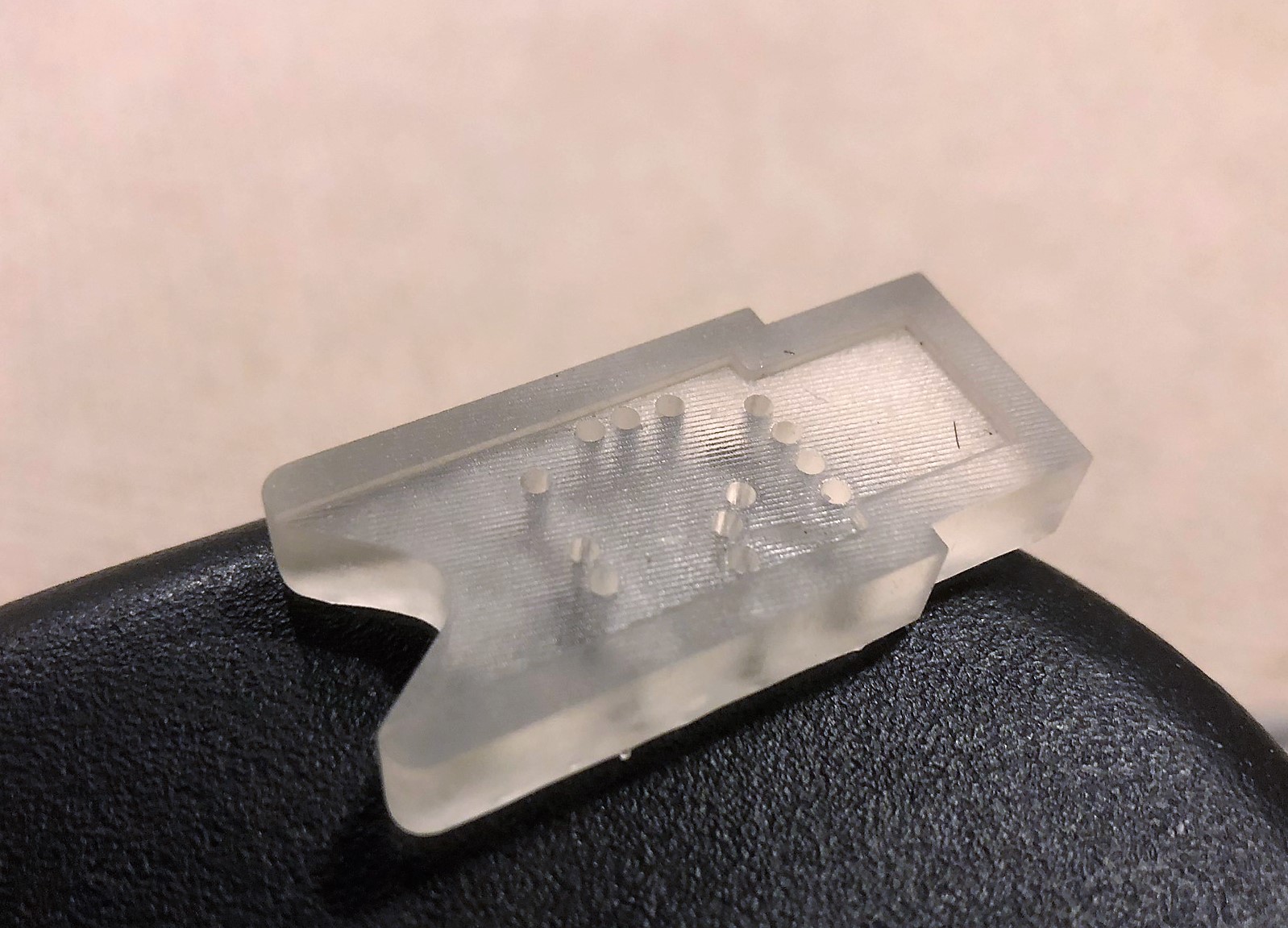
The relevant diameter on the pogo pin is 1.5 mm and it has a press-fit ring that is ~1.62 mm. I set my holes to be 1.61 mm and the pins press fit into them well. You mileage may vary, I recommend printing 2-3 different ones at first.
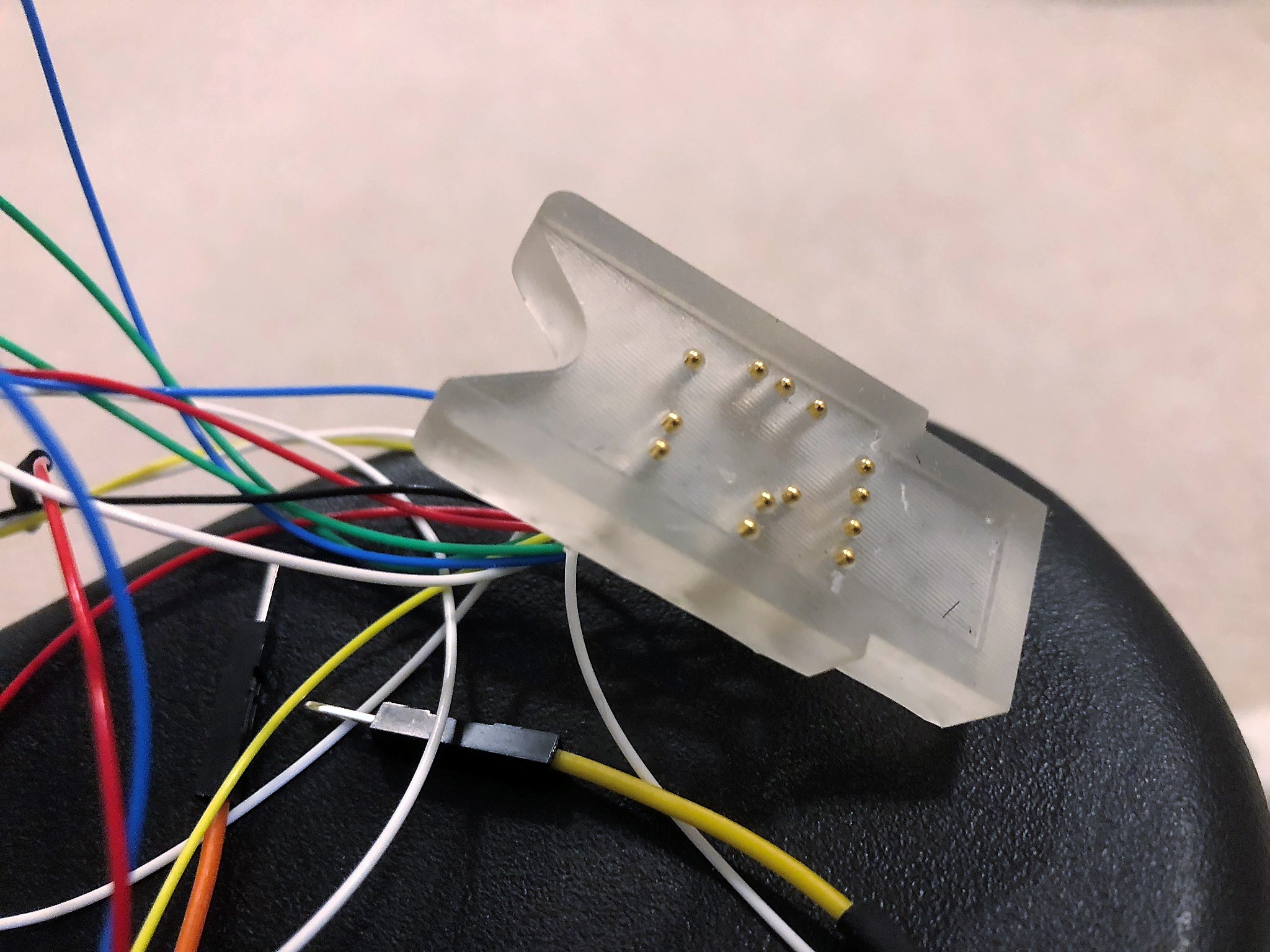
Assemble the jig
The nice thing about solder-cup pogo pins is that they are really easy to solder.
I just soldered a wire to each one and plugged them into my jig.
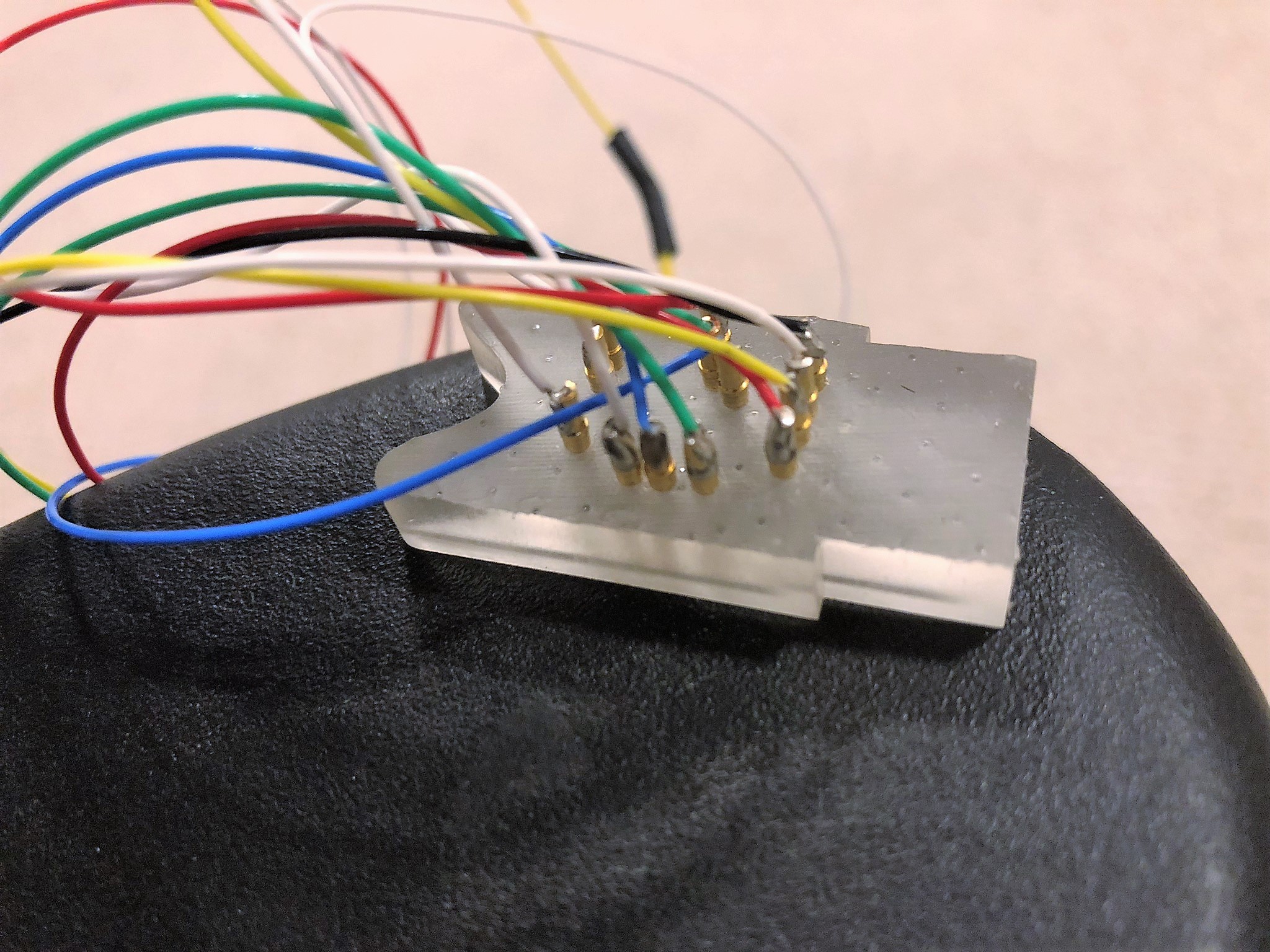
The tedious part is matching the pin outs to your various programmers and UART cables.
Use the jig
Now for the exciting part.
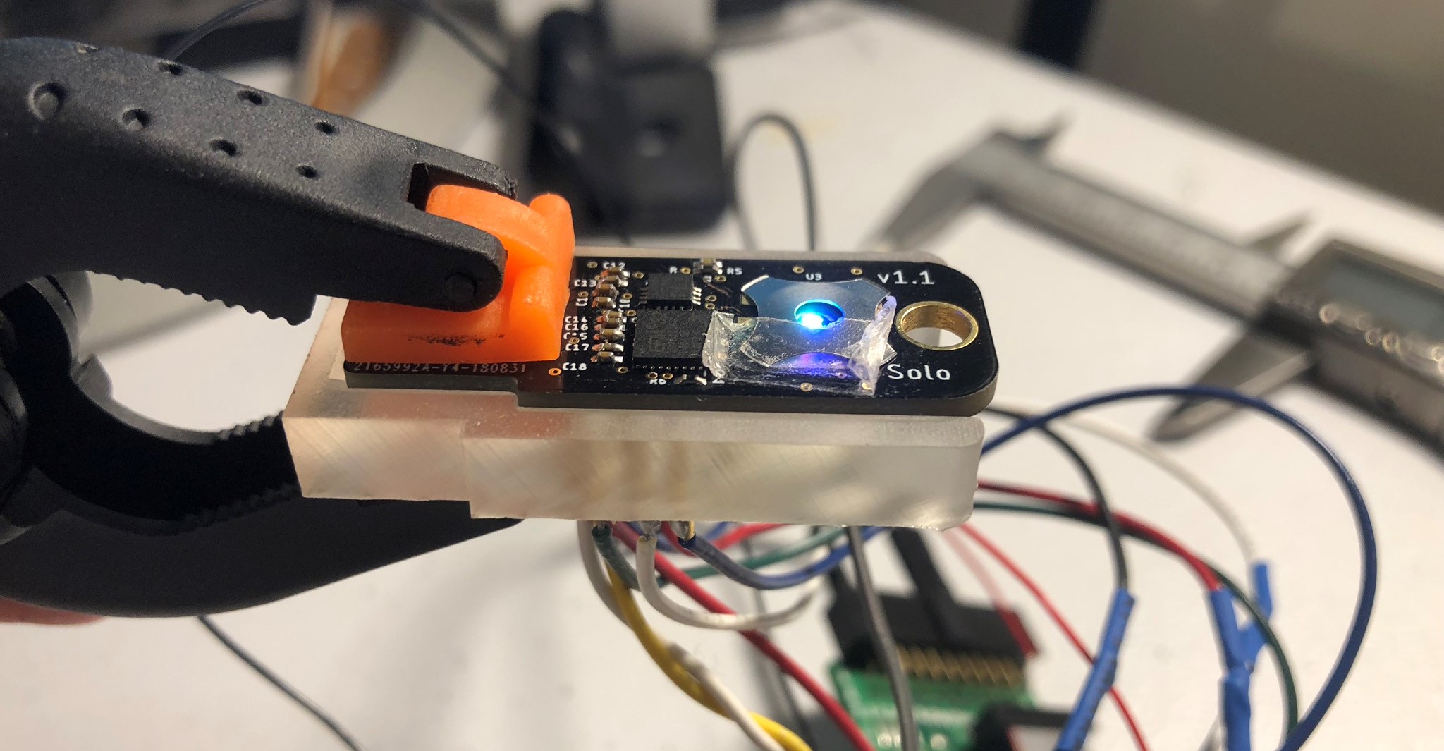
It programs and… It blinks! First try!
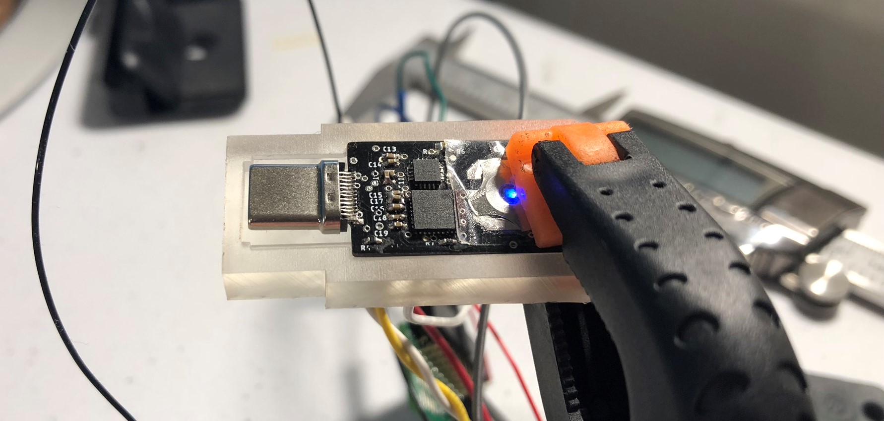
I was able to design my jig to easily accommodate both my USB A and USB C designs.
All in all, I’m pretty pleased with this method and will do it again if needed. If you can recommend any improvements, let me know!
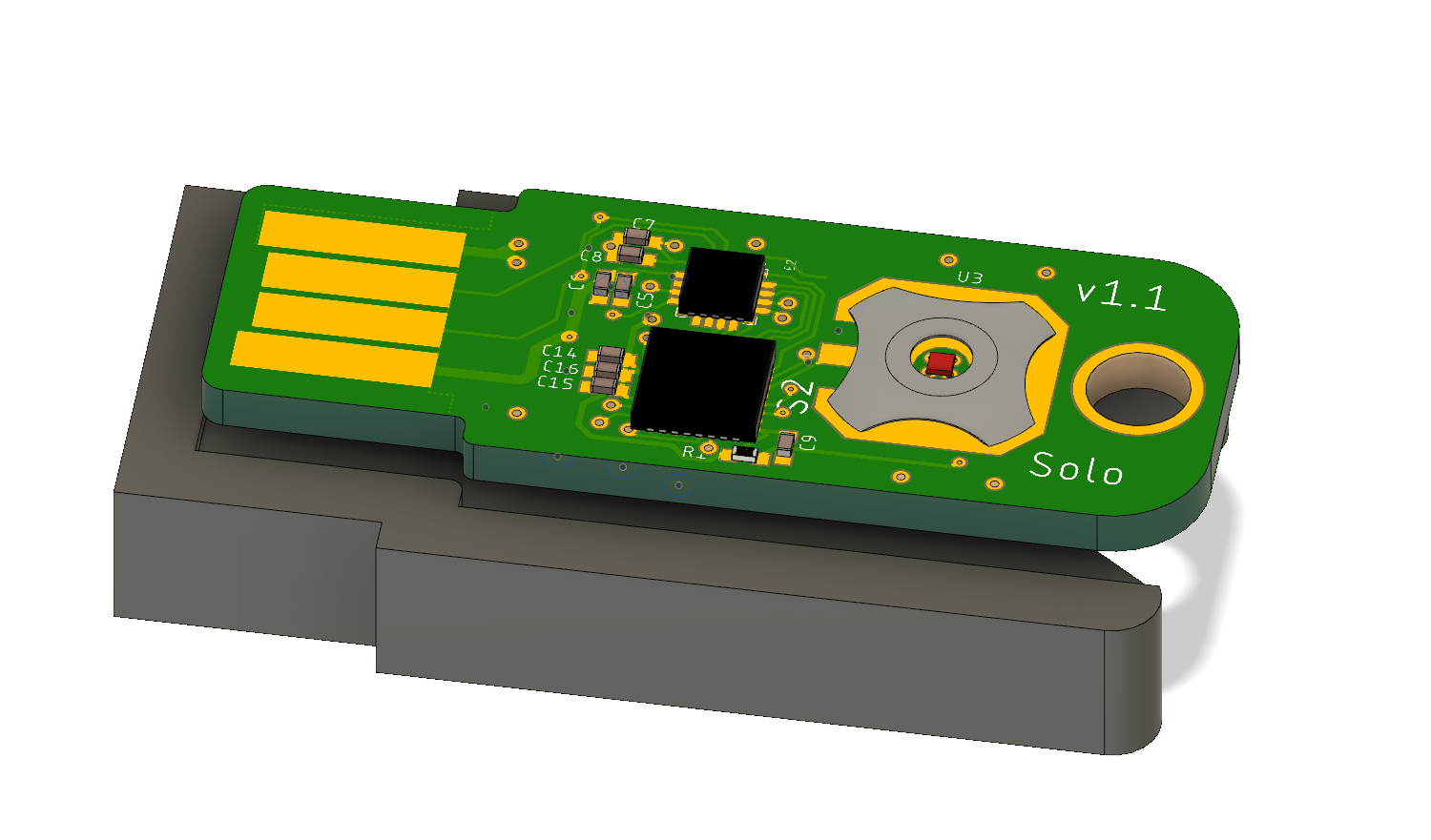
By the way, the design you see is my secure, two-factor authentication token, Solo!