
Designing a clock with levitating arms (part 1)
14 August 2020At some point I developed an interest in magnetic levitation. And I decided to make a clock with levitating arms. I thought it would be a great opportunity to get some more analog circuit experience. It would also be a pretty cool project to show off. Maybe even a Kickstarter.
At the time, I figured maybe it wouldn’t be too hard. There are plenty of magnetic levitating consumer products out there. I could just take a reference design and tweak it to my needs.
It can’t just be any maglev circuit though. It should be able to levitate a magnet in any orientation, so you can leave it on a table or hang it on a wall. Typical maglev circuits work by turning on and off one electromagnet continuously to balance a levitating magnet against gravity. In other words, there is one electromagnet that controls the Z axis position. If gravity is perpendicular to the electromagnetic (like with hanging the clock on the wall), then the typical maglev circuit won’t be able to counter gravity anymore.
I’m not aware of many consumer products that handle “horizontal” levitation, but I did find this product which can. It comes from some Chinese company which develops “EZ Float Technology.” I went ahead and ordered one.
The Reference Design Teardown
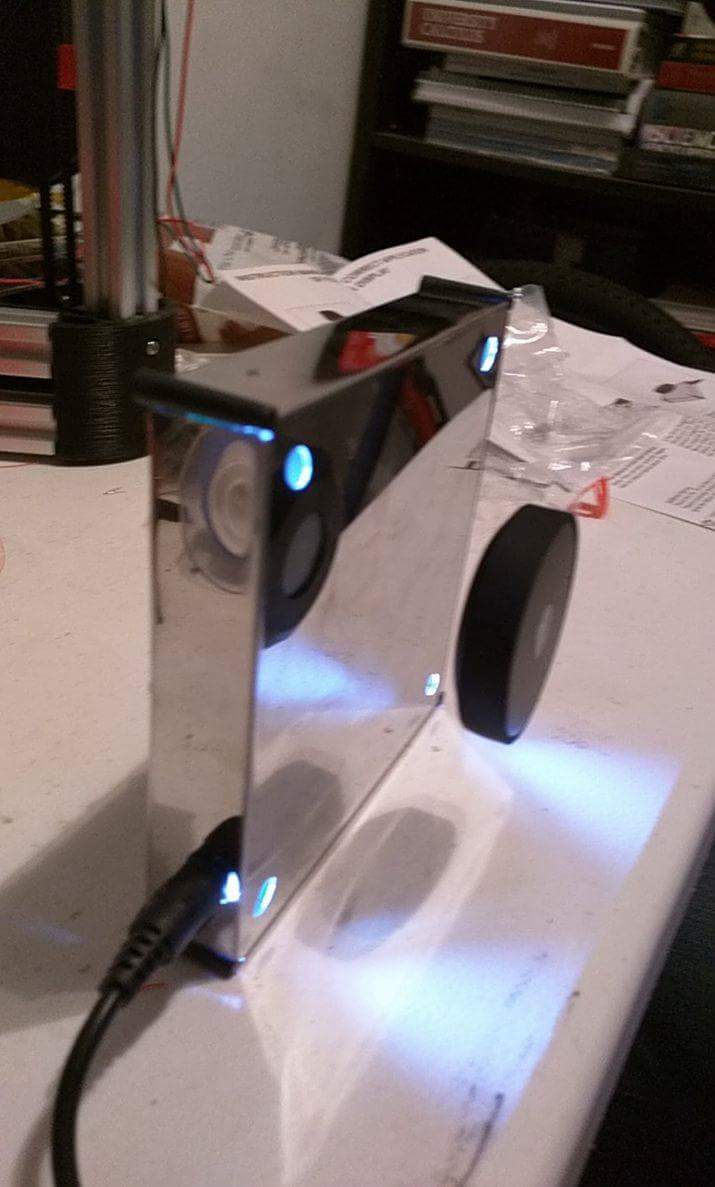
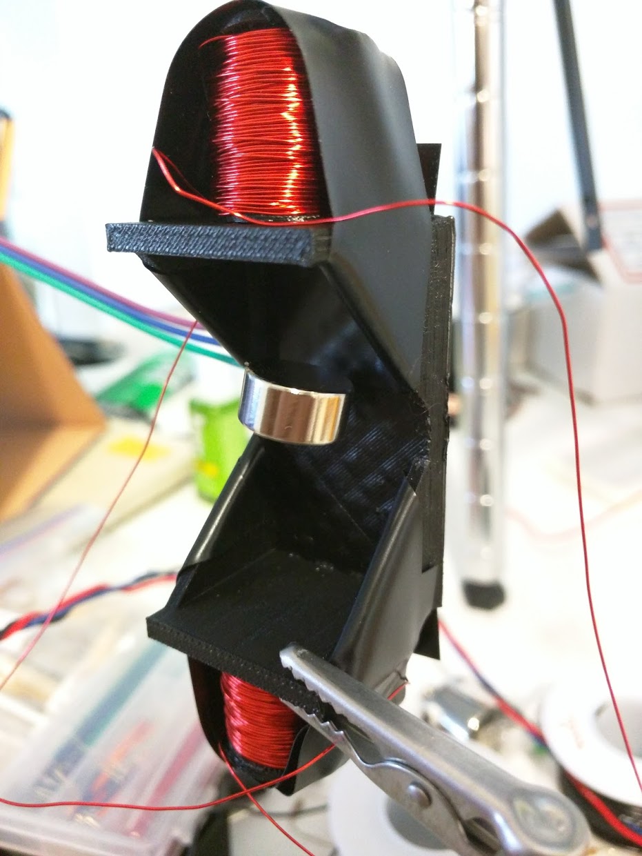
I tried out EZ Float Technology and it works quite well. I wasn’t able to get it to levitate horizontally in one step, but rather had to start it in the vertical position and carefully tilt it up to what you see in the picture. In stability, it only consumes about one watt of power, and up to twelve watts otherwise.
And interestingly, In the vertical position, the magnet holds like a pound of weight without consuming any additional power – how could that work?
It’s a pretty cool product and is close what I would need to make my clock, I would just need to figure out how to shrink the design as the current magnet is way too big.
Let’s see how it works.
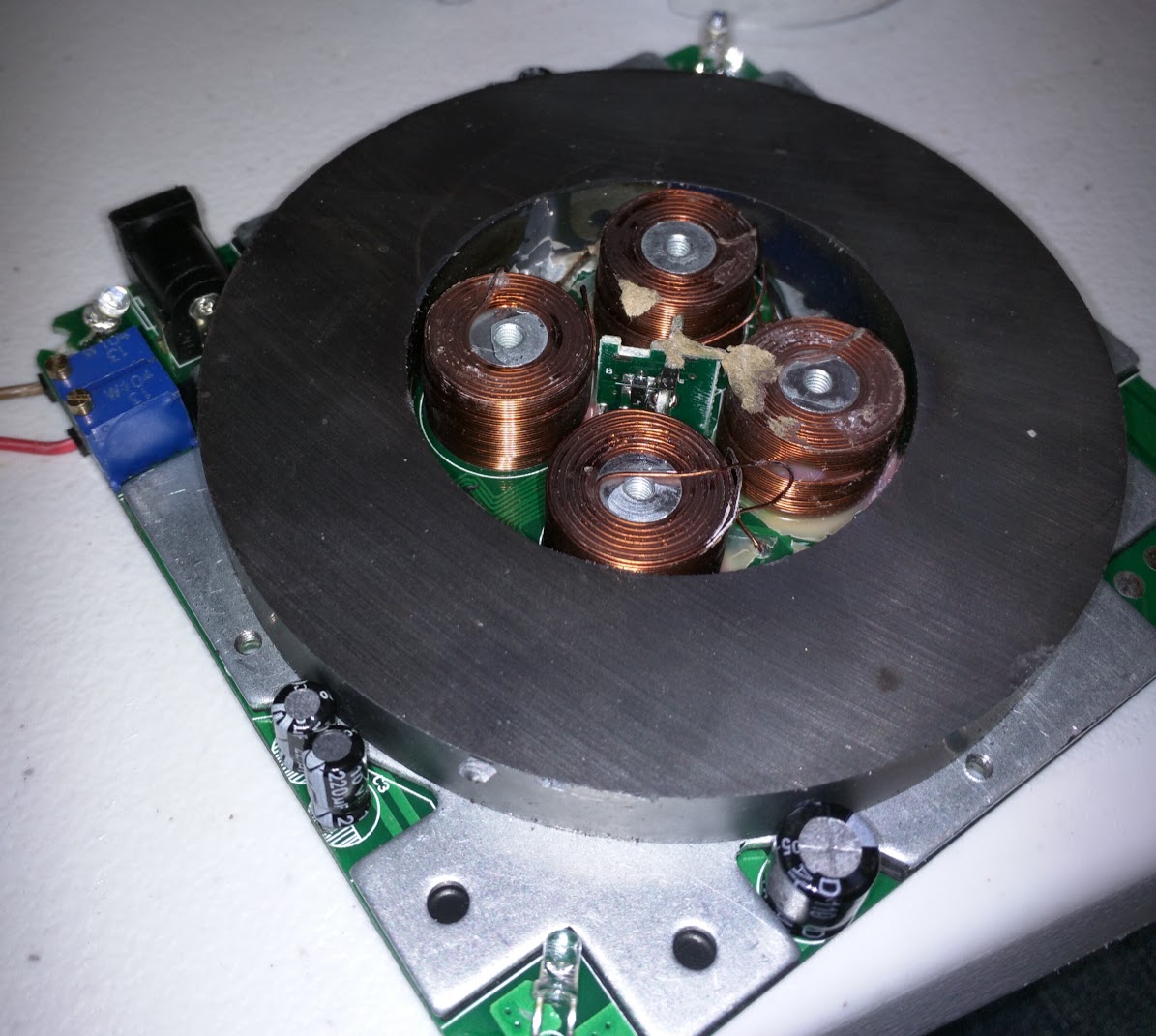
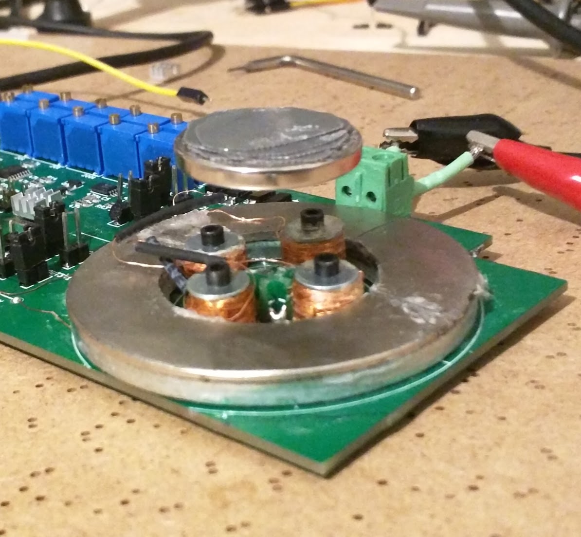
Taking the lid off, you see two components that every maglev design needs: electromagnets and sensors. The electromagnets push or pull the levitating magnet in a controlled loop to keep it centered. The control loop is given input by the sensors.
There are a few important design characteristics you can see immediately.
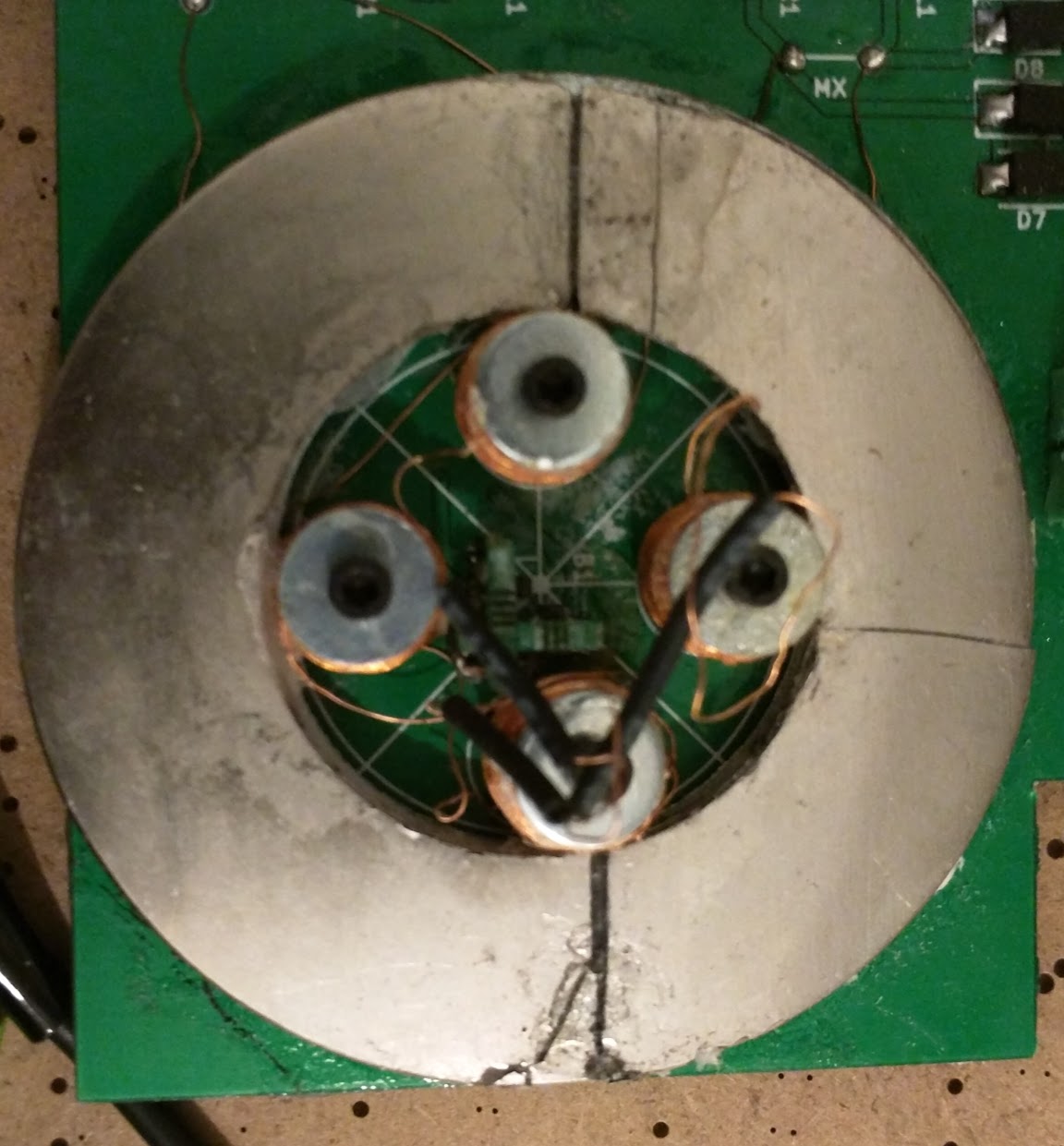
There’s a big ring magnet. At first I wasn’t sure why that was there but it soon became obvious. The ring magnet polarity keeps the levitating magnet from falling toward the PCB. The levitating magnet can only move to the sides, or in the X and Y direction. This is how it can hold additional weight without consuming more power.
This leads to the next characteristic. There are four electromagnets. These are for aligning the magnet in the X and Y direction. They don’t contribute to Z direction control at all (and don’t need to). In a conventional maglev circuit, only the Z axis is accounted for. By adding another axis, you would think you would need one more magnet (not 3 more). But in this kind of configuration, there is no symmetrical configuration that can both balance X and Y axes using 2 magnets. So there are 4.
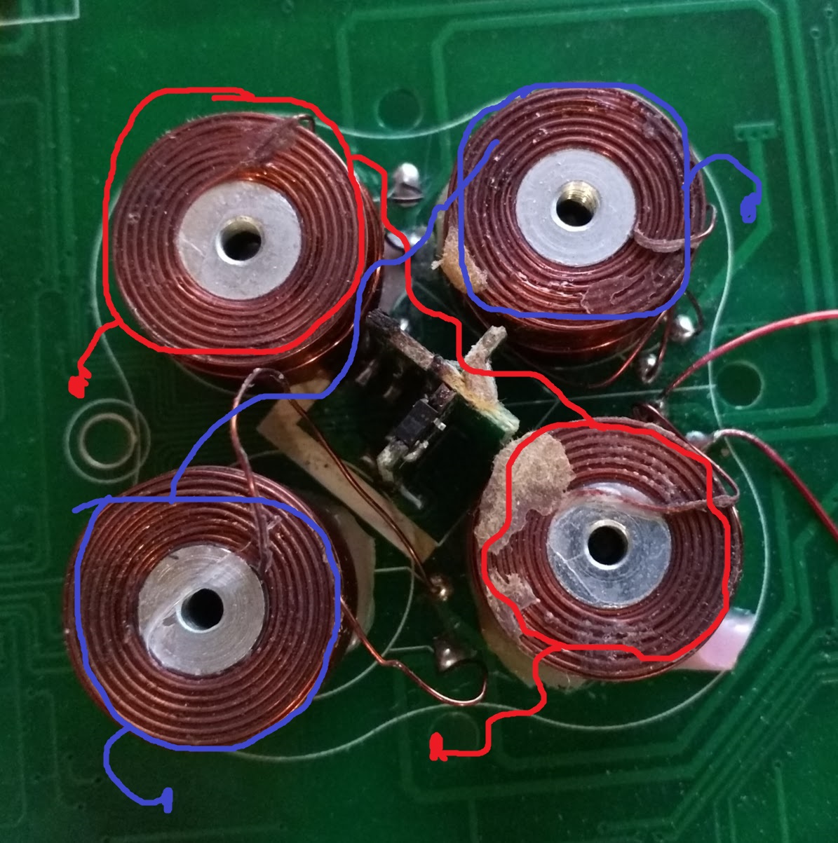
Guess how many electromagnets there really are? Turns out, you can argue there are only two. Each diagonal pair of coils are connected in series. So from a circuit perspective, there are only two coils/electromagnets to drive. So my previous point about there needing to a minimum of 4 electromagnets to maintain control and symmetry is a bit misleading. Since there are only two coils to drive, it makes it much easier to control each coil, using one control loop each.
But if the coils are connected in series, isn’t that just producing the same force on both sides, which cancels out? Not if you switch the polarity of one of them. So a “pulling” force on one corner produces a “pushing” force on the opposite corner. Clever!
On the back side of the PCB are some opamps and H-bridges. More or less what you would expect for a typical maglev circuit, but cut-and-paste twice to handle X and Y control. There are some bidirectional switches as well, which handle changing the electromagnets to run in both forward and reverse.
My first attempt
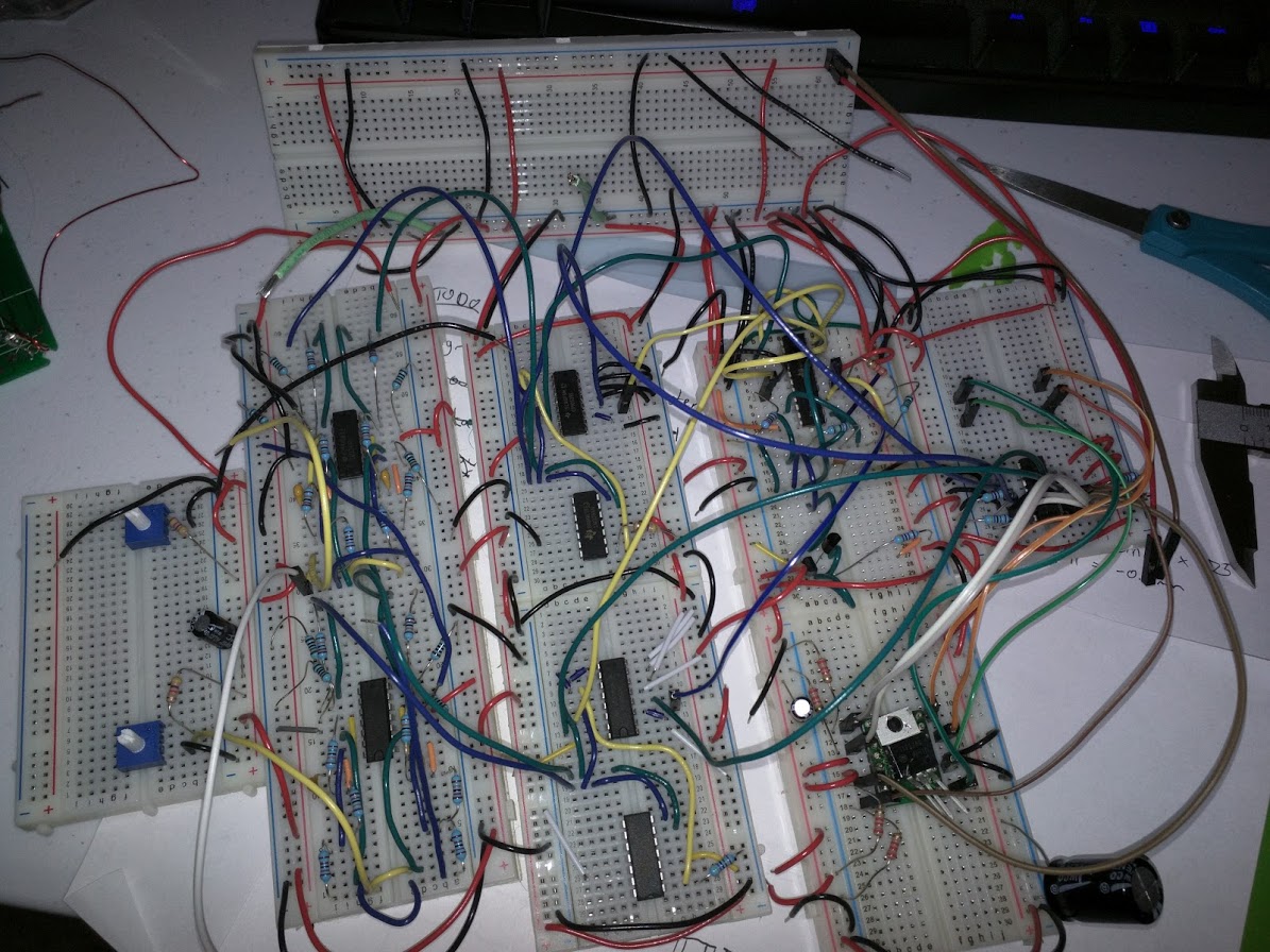
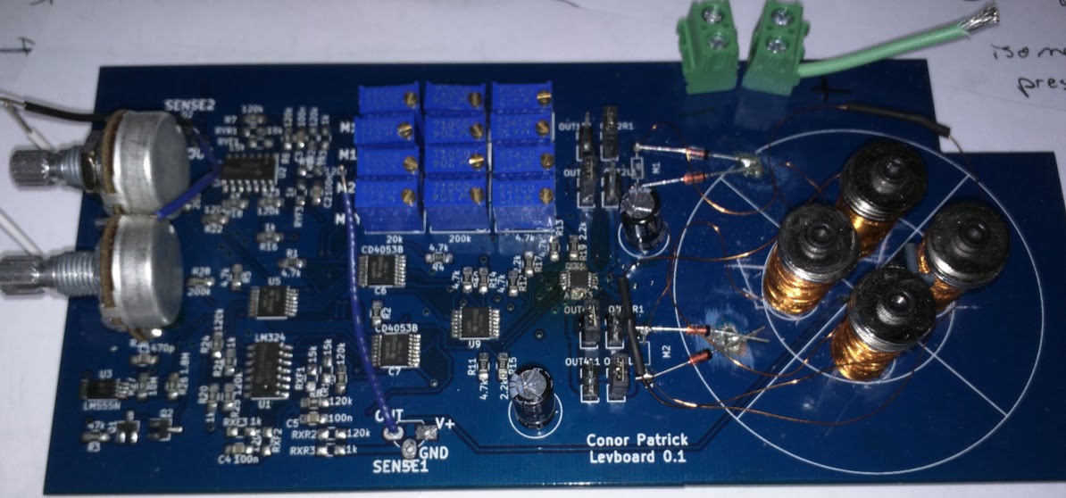
I made a circuit using op-amps, filters, and a couple H-bridges. I simulated it and it did what I expected it to, but there is still a decent amount of uncertainty of what parameters would be best for levitation stability. So I included a lot of potentiometers. Pots for tuning the filtering, the gain, and of course, the reference sensor value representing where the center is.
I breadboarded this monstrosity.
I tested the circuit using a single Z-axis to start and it worked.
But it didn’t work well at all when using a ring magnet and four electromagnets. I made a few mistakes, fixed them, and even laid out a board and screwed electromagnets onto the PCB to make a mechanically stable platform with plenty of pots that would hopefully allow me to converge on the magical control loop parameter solution.
But it wasn’t working. It would levitate for a brief moment, and then oscillate out of control. Every time.
There were a number of problems contributing to this.
Electromagnets caused unwanted feedback in the sensors
The sensors are supposed to respond to the position of the magnet and be indifferent to what the electromagnets are doing. Since the sensors are hall effect sensors and response to any magnetic field, this can be tricky.
One good solution is you place the sensor so it is parallel with the flux lines of the electromagnets and thus picks up zero interference. Only when the levitating magnet moves off-center, will its flux lines have a component perpendicular to the sensor, thus causing a response.
If that is hard to picture, it is okay, I made an MS Paint illustration.
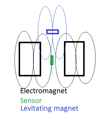
Note how the electromagnet flux lines are nearly parallel with the sensor whereas the levitating magnet flux lines are more perpendicular to it.
I designed my sensors to sit at about halve the height of my electromagnets. However, this wasn’t good enough. It’s hard to estimate the exact center of the sensor and the center of the flux lines on a home brew electromagnet. So there was always a significant amount of interference.
I solved this by using a standoff as the electromagnet core and putting a set screw in it. This allowed me to offset the center of the flux lines by moving the set screw up and down within the standoff core. It works pretty well.
I’m bad at control loops
Admittedly, this was the bigger reason my circuit didn’t work. When the levitating magnet oscillates out of control, it is mostly due to overshoot. Basically, if the magnet is off center by 1 mm, it will get pushed over to -1.2 mm, and then to 1.5 mm, and then -1.9 mm, and then 2.6mm, and then WHAM. It slams into the side of the ring magnet. This kills the ring magnet.
The solution to overshoot is to subtract away a component of the derivative of the position (i.e. the velocity). So when the magnet gets from 1 mm to 0.2 mm, it is going faster and the controls should start pushing the opposite way to slow it down in anticipation of overshoot.
This should be familiar to those that have worked with PID loops. The P (proportional) term corresponds to the control loop just responding based on how far away the magnet is from the center. The D (derivative) term is the counter to overshoot. The I (integral) term isn’t needed for my system but it’s good to research it if you don’t know it.
My original design had some high pass filtering which acts as a “D” component. But it wasn’t good enough. I switched to a Teensy and wrote the PD control loop there to get something quickly.
I made a pretty good workflow for tuning the PD parameters and it responded about every 10 μs, which is pretty good considering the oscillations are above .01 s in period.
But no matter the PD parameters, it still doesn’t work. If I “fix” either the X axis or the Y axis with a jig, it works. But never together. And overshoot wasn’t the issue anymore. It would be stable in the X and Y, and then start oscillating in the Z, which would mess with my precious X and Y PD parameters and throw it off. I guess when all electromagnets are on, it pulls the magnet down a bit, and when the electromagnets switch direction, the magnet shoots up, causing the oscillation.
It needed just a wee bit of damping to slow it down. I added some steel sheet cutouts to the top of the levitating magnet. This damps it by making it heavier. It also causes an attraction to the ring magnet and I think that contributes to damping.
And finally, it works!
The next improvements
The design is still far from perfect. It only tolerates about a 30 degree change in orientation before the magnet falls. I need at least 90 degrees. My PD parameter tuning may be over but there are some more parameters I need to tune.
Coil inductance. A larger coil inductance means it takes longer for the control loop to actually change the magnetic field. A series inductor acts like a low pass filter. So while my control loop frequency was about 100 KHz, the inductance of my electromagnets actually limits it to somewhere between 1-10 KHz. I need to try reducing the number of turns per coil. If I halve the number of turns, it halves the magnetic field strength and quarters the inductance. This might be a good trade-off.
Electromagnet height. Making an electromagnetic longer provides diminishing returns for increasing field strength. So reducing the length could provide another good inductance vs. field strength trade-off.
Levitating magnet weight and iron component. Making the magnet heavier certainly adds a damping effect. But I would like it to be light enough to hold at 90 degrees. And adding magnetic material to it causes an attraction to the ring magnet, which I think provides a damping effect but I’m not sure.
I’m pretty sure that the coil inductance and the magnet weight are pretty related. I think by reducing the inductance, I’ll be able to support a smaller magnet. Another thing I could do is increase the driving voltage but that adds some circuit complexity.
Parameter hell
I would really like to model this and make some well founded estimates on what everything should be, based on my 90 degree orientation constraint and optimizing for a small magnet size. But I’m not sure how to relate everything. If anyone could provide some thoughts on this, I would greatly appreciate it.