
Proof of concept for a reconfigurable mold
25 June 2020If you want to mass produce some physical product in a short amount of time, chances are you would need to get a mold made. Most plastic parts get made via a plastic injection molding process, where molten plastic is injected into a mold cavity under high pressure, cooled quickly, and then ejected. For mass production to work, the mold needs to be durable enough to last for thousands of injections. Commonly they are made out of steel.
It is nontrivial to create one of these molds as it costs on the order of thousands of dollars. Thus it can be intimidating to get into this process at first because of the cost. If molds could be reconfigured such that they could easily be reused for different parts, then a lot of money could be saved.
I recently got interested in plastic injection molding and also wanted to get better at mechanical design. So I thought I would try to design my own reconfigurable mold. It ended up not being practical and more of a proof of concept. Here I show what I made and its results.
Reconfigurable Pin Tooling
Reconfigurable pin tooling is an idea where you have a discrete bed of pins that make up the mold surfaces. Each pin can be actuated to replicate any “moldable” part design. The following figure from [1] shows the basic idea using 2 surfaces. A complete mold would need 6 surfaces.
Reconfigurable pin tooling is not a new idea. In fact, patents for reconfigurable pin tooling systems go back at least 1-2 centuries [2]. There are many different designs. Some put smooth, elastic surfaces above the pins and others devise clever ways to actuate each individual pin.
My design
I tried to make it as simple as it could possibly be. I didn’t look into actuating each pin but figured I could press the matrix of pins into the surface of the part that is being molded. Then, there would just need to be some way to “lock” the pins in place. After locking the pins in place, you have 1/6 of the possible surfaces needed to replicate the part in a mold!
As for the locking mechanism, I decided to make a 2-dimensional vice that would hold the pins in place from 4 sides. I coded up the design in openscad and parameterized it such that I could get renderings of it in open and closed positions.
Here is a rendering of the vice opened with a bed of pins floating in the middle.
Now the pins have been “pressed” against a surface of an arbitrary part, effectively creating a mold of it.
By closing the vice, the pins are held in place.
I figured this would be enough to start with. The design could be implemented by making parts for the walls of the vice and ordering parts for various rods, nuts, and bearings. Also need to find a source for making ideal pins.
Implementation
I 3D printed parts for the vice and also used parts that I ordered from McMaster. I used openscad for the design which I really like since it’s fully parametric. So I can design the vice any way I want at first, and when I pick out parts from McMaster, I just need to change a few variables to ensure the design will fit the parts. Going the other way around (fitting the parts to the design) isn’t always so easy. (Edit: I’ve since changed to Fusion360. Way better for most things.).
Here is my 2D vice. By turning the threaded rods with the thumb screws at the end, it pushes on the internal walls, which slide on nylon bearings. So to tighten the vice completely, you need to turn six rods (not convenient, but works).
Here is the vice tightened on a bed of pins.
For the pins, I just used the smallest steel key stock available online. I found the smallest to be 1/16in x 1/16in on McMaster. The pins, while each individually are cheap, still end up being the most expensive part of the design. This is because you need a lot of them to implement any moderately sized surface. To avoid high costs I designed for a surface that was only just over 1 square inch. Since it’s pretty small, the 1/16in key stock resolution really sticks out. It still works, but for this to be practical, the ratio of surface size to pin cross-section would have to be much bigger or parts will look too chunky.
I tested the mold using silicon molding compounds (not under pressure). The part I molded against was a simple 6 sided die.
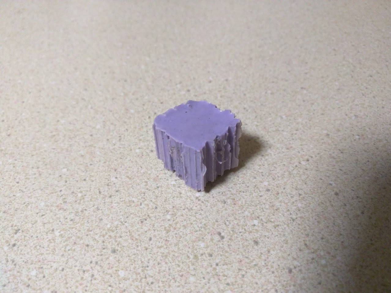
As you can see, my replicated 6-sided die is pretty chunky! I didn’t bother to test its fairness. While this molding technique is certainly reconfigurable, resolution takes a hit. It would also have some serious problems when put under high pressure. For example, molten plastic would seep in-between the pins.
I tried brainstorming some ideas to fix problems with “chunkyness” and high pressure. Maybe the pins could be coated with some temperature and pressure resistant glue before using the mold. Then it could be removed mechanically or chemically when it comes time to reconfigure. Maybe the molten plastic / silicon could be placed in a special balloon that would inflate inside the mold under pressure, and could be removed after the part cools.
I haven’t really come up with anything that I really liked. If anyone has any ideas, I would love to hear them.
Putting the pins in the vice
One problem that came up was that it was really hard to place the pins in the vice and maintain that they all be square with respect to one another. If you simply place them in the vice and tighten, they would all be a jumbled mess.
I solved the problem by creating a fine stainless steel mesh that I could put the pins inside first. It serves as an alignment tool before placing the pins in the vice. Putting roughly 300 pins in the mesh wasn’t fun but it worked quite well.
I was able to get these meshes made by OSH Stencils, which is a company that makes cost effective stencils for soldering electronics. Turns out it is perfect for making pin matrix alignment tools. They use an industrial laser to cut 0.004” stainless steel sheet. And the tolerances are really good, all around 0.001”. I got my stencils for like $15-20.
Conclusion
Reconfigurable pin tooling is pretty cool but far from practical I think. It is expensive to get enough pins to mold large surfaces, however, it is worth while if the molding process worked well. But as far as I can tell, it’s no where close to working as well as conventional molds. Problems with “chunkyness” and pressure remain. If you have any ideas, let me know!
[1] Bahattin Koc, Sridhar Thangaswamy, Design and analysis of a reconfigurable discrete pin tooling system for molding of three-dimensional free-form objects, Robotics and Computer-Integrated Manufacturing, Volume 27, Issue 2, April 2011, Pages 335-348, ISSN 0736-5845.
[2] Munro C, Walczyk D. Reconfigurable Pin-Type Tooling: A Survey of Prior Art and Reduction to Practice. ASME. J. Manuf. Sci. Eng. 2007;129(3):551-565. doi:10.1115/1.2714577.
[3] My openscad design files, https://github.com/conorpp/reconfigurable-pin-matrix